How Control-Allocation for Multirotor Systems Works
A mathematical explanation of how drones function.


Seeing drones fly always makes you think how it can hold itself stable in the air? Multicopters and their wide-ranging applicability made them to one of the most innovative means of flight and transportation of various kinds. However, in the background run complex mathematical calculations to precisely follow control inputs with respect to environmental influences.
Maneuvering a multicopter in 3-dimensional space is conducted by specific rotational frequencies of each individual rotor, whereby the system is able to perform the desired movement. In this process, certain rotors are accelerated to shift the orientation of the multirotor system corresponding to the control input of the pilot. On the innermost inside of the flight controller (the computer of each drone) lies a control allocation program. With the pilot’s input it establishes various input information in form of matrices and performs a number of linear algebra transformations and computations to calculate the output values. The interesting thing on a mathematical level is that there are infinite options with increasing rotor count on how to distribute the rotational rotor speeds. But first, let us talk about some basics.
Configuration
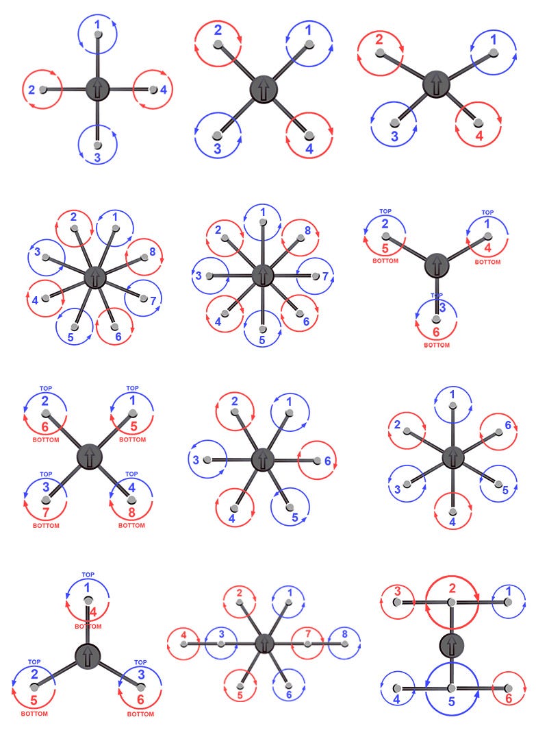
The setup and position of the single motors are the most important information for the mathematical computation. This also includes the weight and the position of the center of gravity. This is the reason why a drone crashes or does not fly stable anymore when you add an unforeseen payload. There are many different configurations or layout patterns for multirotor systems. They range from the most common collocations such as Quad-, Hexa-, and Octocopters to rather uncommon arrangements like Coaxial-, Bi-, Tri-, Penta-, or Heptacopters.
The information about the setup is essential for each individual drone and will play an important role in the mathematical equations.
Dynamics
To control drones, certain rotors are speed-up or slowed down to move the orientation of the multirotor corresponding to the pilot’s control input.
Usually multicopters are powered by fixed-pitch rotors which means the single blades cannot be adjusted in pitch. While spinning, they not only create thrust but also create torque about its own axis which would make the drone spin. In order to counteract, one half of the rotors are spinning clockwise, the other half is spinning counterclockwise. The rotor torque is cancelled when they are operating at equal speeds, and the aircraft can hover in a stable manner. For ascending and descending, the rotor speeds are equally in- or decreased.
While hovering, ascent and descent maneuvers are quite easy to calculate, pitch and roll need a certain thrust and torque control to gain the desired control output and still keep the same height. The following movements are explained with the simplest configuration, a quadcopter. If the aircraft needs to roll, the propeller speed must be accelerated on one side of the roll axis and decelerated on the other side. This results in a lateral movement due to the changed thrust vector orientation. The same applies to pitch control about the pitch axis.
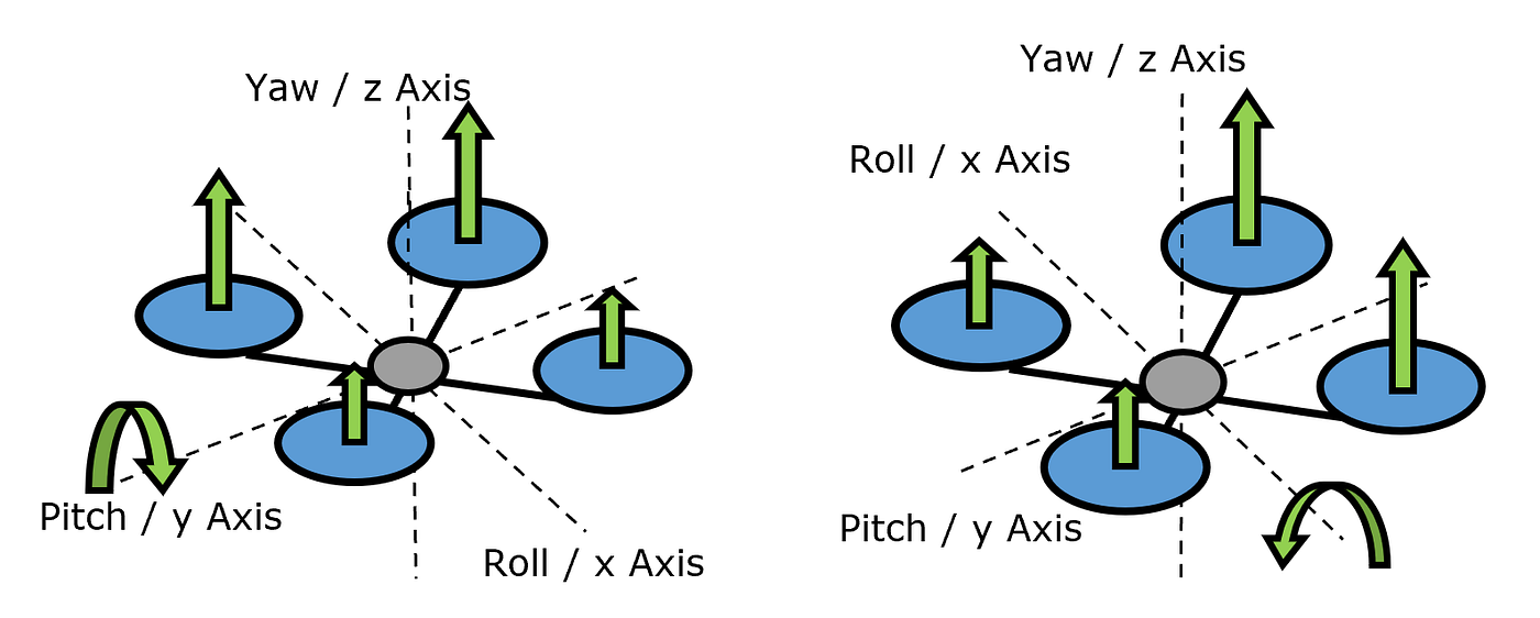
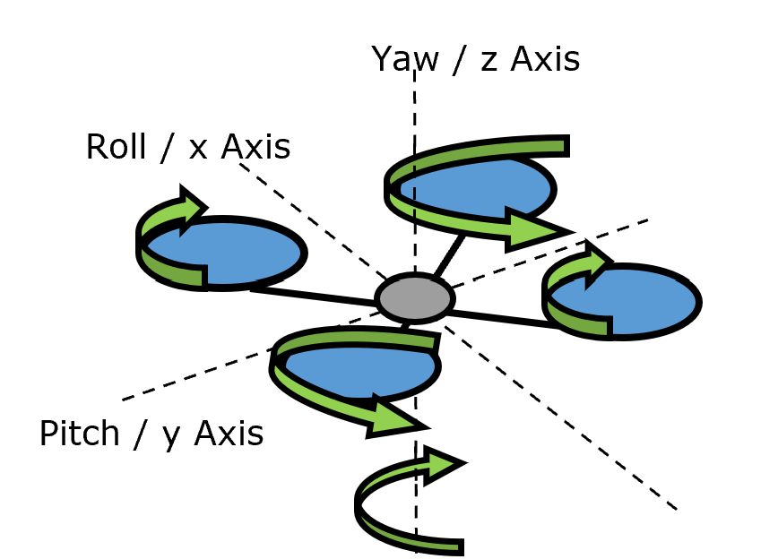
To rotate the multicopter about its own axis or to change its orientation, one half of the opposite laying rotors are accelerated, and the other half of the opposite laying rotors are decelerated. This change overrides the torque compensation and the multicopter rotates about the yaw-axis.
Physical Basics
Knowing how drones can control itself, we can start with the physical basics that are implemented in the flight control laws. The equation used in flight controllers for thrust of a rotor is defined as follows:

Because k is a constant thrust coefficient which is only depending on the geometry of the rotor, the thrust is directly proportional to the rate of rotation nsquared.
Every propeller also creates a torque which counteracts to the turning direction of the propeller. It is also proportional to the rate of rotation n squared:

In this equation k is also a constant moment coefficient depending on the rotors’ geometry.
Finally, we have to calculate the torque or moment around the x-axis and y-axis of the drone depending on the thrust T of one rotor and its distance l to the axes:

With these three equations we can establish a system of linear equations so that the rate of rotation for each propeller can be calculated in the most efficient way for a given control input.
Basic Mathematical System
What the flight controller has to solve every 2–3 milliseconds is a linear system of equations. Every line represents one type of input movement of the multicopter. In this case we are only looking at the system of a quadcopter, but the system has no limitations in size.
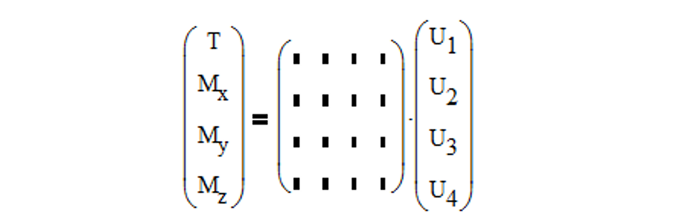
The rotational rates n squared are substituted by the rotational speed U to give a better overview. T stands for the total thrust, and M(x,y,z) for the moment or torque around all three axes of the drone.
The matrix in the center called B-matrix varies for every multicopter and describes the configuration of the system that is described in the first section. In our case we are looking at a very simple, symmetrical quadcopter. It includes the two different rotor constants k, the distances l between the rotors and the center of gravity and the different angles phi that the rotors have counted from the forward flight direction around the center of gravity.
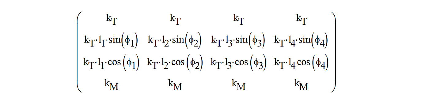
Finally, we can see what the flight controller’s deepest task is all about: Calculating the vector U, the rotational speeds for each rotor, in this linear system. In the following section we will quickly solve the system. Do not worry if you cannot understand it at first glance if you are not into matrix operations.
Mathematical Solution
Solving the equations for U is done with the inverse-matrix of B:

Because of the multiplication rule for matrices (valid only when the number of columns of the B-matrix equals to the number of rows of the TM-matrix) it is necessary to make use of the so-called pseudoinverse matrix to get a 4x4 matrix out of a 4xn matrix, or in general to transform a non-quadratic matrix into a quadratic one. If we would restrict it on a quadcopter, it would not be necessary because the B-matrix is already quadratic. However, this would cover only one of many configuration possibilities.
The creation of a pseudoinverse matrix requires a combination of the matrix-operations inverse, transpose and multiply as visible in the following equation:

Applying this to the B-matrix and solving the equation for U by multiplying it with TM will give us the necessary rotor speeds in the most efficient allocation.
Example and Result
To visualize and verify our calculation, let us take a look at the following drone:
- symmetrical octocopter
- 6 kg take-off mass
- equally distributed rotors with a distance of 0.4 m from the center of gravity
- rotor speed in hovering of 4000 rpm
Our high-level control input is “Fly Forward” which on deeper level requires to rotate around the y-axis as you can see in the picture of pitch-dynamics. Therefore, our control input My must be a realistic positive value like 1 Nm, which means the drone would rotate with a force of about 2.5 N or a mass of 0.25 kg pushing in 0.4 m distance.
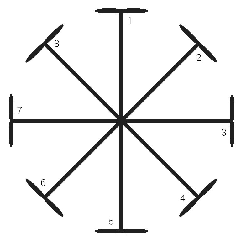
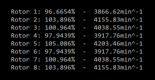
The control allocation program delivers following result which is not at all easy to understand. Since we have 8 rotors, there are infinite possibilities to achieve this desired control input. But you can try to imagine it with help of the configuration above. Rotor 1 lays in forward flight direction.
This is how one of the deepest and most important loops in a flight controller works. However, in most flight modes it is not directly related to the control input of pilots but rather to control inputs of the flight controller that used the pilot’s commands in other computations like position hold and requires our calculation for higher-level control loops. Especially drones with more complex flight modes that fly almost autonomously must work on additional estimations like the optimum flight path, coordinated turns and position control and this would lead us deep into flight dynamics.
Hopefully, you could learn something new while reading. I am looking forward to your comments!
Sources:
Lay, D., Lay, S., McDonald, J., “Linear Algebra and its Applications,” Fifth Edition, Pearson, United States of America, 2016.
Johnson, W.: Helicopter theory, Univ. Press Princeton, New Jersey, 1994
Quan, Q.: Introduction to Multicopter Design and Control, Springer, 2017